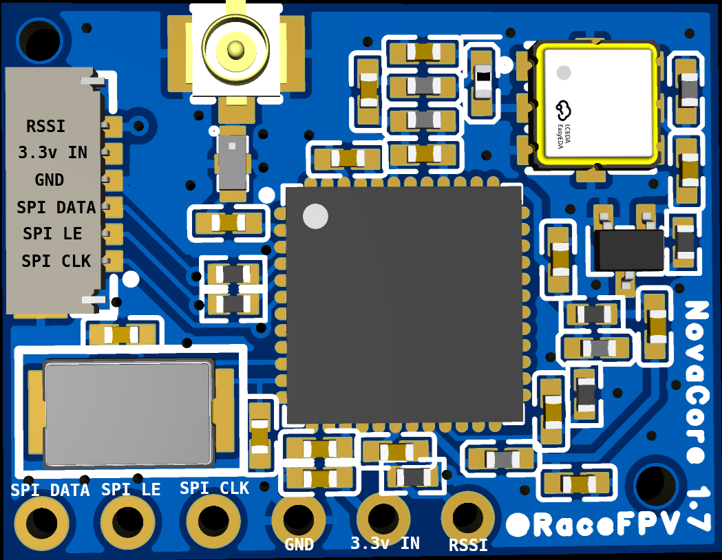
Novacore spec/datasheet
Summary
Full 5.8GHz band detection
RTC6715 SPI-controlled tuning
Analog RSSI output
3.3V INPUT ONLY
u.FL antenna connector
RX5808-compatible pinout
optional 6P 0.8mm connector
M1.2 screw mounting
Wiring
You can choose to wire up the Novacore boards using -either- the 0.8mm jst connector OR the holes at the bottom of the board. Please do not attempt to connect/wire up both at the same time.
The board expects ~3.3V input, there is some on-board filtering but be sure you do not feed 5v in, as this will damage the components.
Dimensions
Width: 21.7mm
Length: 16.7mm
Distance to first pin (from left): 1.143mm
Pin spacing: 2.54mm
Top left screw mount:
Distance to hole center:
Left side: 1.143mm
Top side: 1.143mm
Bottom right screw mount:
Distance to hole center:
Right side: 2mm
Bottom side: 2mm
Signal Detection
Novacore boards beginning with version 1.5 have a custom RF frontend designed to work with both 25mw and 200mw pilots. The signal is as linear and close range as possible without missed lap timings. In addition, the optional u.fl antenna can help in some larger environments, or it can be swapped out for a patch antenna to further refine the gate signal window.
Antenna options
By default it is recommended that the NovaCore board is operated without an antenna present. This means the u.fl connector acts as a directional antenna with a targeted beam pointed ‘up’ if looking down at the top of the board. If you need more general detection, or have pilots with weak/low 25mw transmitters, The lowest dbi patch antenna possible is recommended, around 2-3dbi.